
Quick Answer
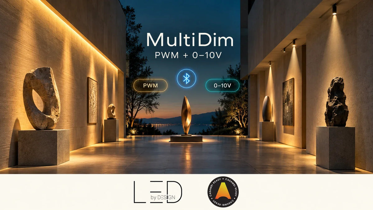
Casambi MultiDim combines PWM outputs for compatible constant-voltage LED strips with 0–10V outputs for compatible driver control. Use PWM where the controller directly dims the low-voltage strip circuit; use 0–10V where a separate driver accepts an analogue dimming signal. Select the exact profile and electrical arrangement for your project. The controller does not replace the power supply or make every driver compatible.
Why one project may need two output types
A lighting scheme might include a concealed LED strip and a luminaire supplied with its own dimmable driver. Both should feel simple to the person using the room, but their electrical interfaces can be different. Choosing controls only by the room name or the word “dimmable” can leave an installer with components that cannot work together.
The LED BY DESIGN MultiDim-PWM & 0–10V Controller is intended to address these different control roles. Its published description lists two PWM channels and two 0–10V outputs. The practical task is to determine which output type each lighting load needs and which configuration the supplied device supports.
This is an application-planning guide, not a terminal-by-terminal installation manual. Start with the fixture and strip documentation, then confirm the controller revision, profile and wiring instructions before installation.
What does the PWM side do?
PWM means pulse-width modulation. In a suitable constant-voltage strip circuit, it changes the proportion of time the output is on to adjust perceived brightness. The connected strip still needs an appropriate DC supply. Selecting PWM control does not turn a constant-voltage strip into a constant-current load.
Think of a display shelf with a conventional white LED strip. If the entire connected run should brighten or dim together, this is the kind of requirement for which a suitable PWM output can be considered. Check strip voltage, current, run length and installation conditions. If the brief instead requires independently moving colours along an addressable strip, read our SPI versus PWM buying guide.
What does the 0–10V side do?
A 0–10V output provides a control signal to a driver designed to accept it. The driver remains responsible for supplying the LED load. Its dimming input and its power output have different jobs, so the analogue control connection should never be treated as a power source for an LED strip.
This arrangement can be useful when a selected luminaire already has a compatible driver. However, “0–10V” on two product descriptions is only the beginning of a compatibility check. Confirm the electrical control interface, permitted connection arrangement, dimming behaviour and any requirements for switching off. Ask the driver supplier for its control documentation rather than inferring behaviour from a marketing label.
A demand for complete darkness deserves particular attention. Verify whether the actual driver supports dim-to-off, its minimum light level, and any required switching arrangement. Do not promise that a zero command always disconnects the load or removes power.
PWM and 0–10V at a glance
| Question | PWM role | 0–10V role |
|---|---|---|
| What is being controlled? | A compatible low-voltage strip circuit | A compatible driver's dimming input |
| What needs matching? | Supply voltage, channel arrangement and load | Driver interface and control behaviour |
| What powers the LEDs? | The selected DC supply through the designed strip circuit | The selected LED driver |
| What should a sample test show? | Stable dimming across the intended range | Useful dimming range and expected off behaviour |
Where MultiDim can fit
A retail display with different lighting layers
Imagine a display with a strip in the joinery and separate accent lights using compatible analogue-dimmable drivers. The designer wants both layers in a presentation scene, but also wants to adjust their balance. MultiDim is a candidate worth evaluating because the project contains both interface types. Confirm the required profile and channel mapping before deciding how many devices the design needs.
A white-light project with a colour-temperature brief
The official product description includes tunable-white applications. That does not mean every two-output arrangement gives the same brightness and colour-temperature controls. Document the load or driver’s expected inputs and confirm how the selected Casambi profile maps user controls to them. Test the warm and cool ends, intermediate settings and low light levels using the actual components.
A refurbishment retaining existing drivers
If existing luminaires are staying, first identify their drivers and accessible control connections. A compatible 0–10V path may be worth considering; an incompatible driver may require a different solution. The presence of a wireless control layer does not remove the need to inspect power and control wiring. Record access constraints before promising an uncomplicated retrofit.
Six checks before specifying MultiDim
- Identify every load. List the strip or luminaire model, supply requirements, driver model and desired control. Keep this schedule separate from room names so that two visually similar fittings are not assumed to be electrically identical.
- Match the output interface. Assign conventional strips to the appropriate PWM arrangement and compatible drivers to the appropriate analogue-control arrangement. Do not connect a bare LED module simply because its wattage seems small.
- Use the exact electrical limits. The current LBD listing gives a 12–48VDC input range and specifies a lower current limit at 48V. Treat ratings as conditions to check, not as interchangeable headline numbers. Verify channel and combined loading for the actual revision.
- Confirm the profile. Obtain the supported profile and channel mapping for the required application. Do not assume every physical output is an independently selectable app zone, or that all possible combinations are supported simultaneously.
- Check installation conditions. Review mounting, access, temperature, enclosure requirements and cable routes with the installer. Leave practical access for service and configuration rather than burying the controller behind a finished surface.
- Commission a representative sample. Test each load independently and then in the intended scenes. Review dimming, colour-temperature behaviour where applicable, switching and recovery after power interruption. Record the accepted settings for handover.
When should you consider another controller?
A mixed-interface device is most useful when its capabilities match the job. A project needing more PWM colour channels may call for a different PWM model. An addressable feature needs its supported digital interface. A DALI driver needs an appropriate DALI control solution. Begin with the load and required behaviour rather than selecting a versatile device and trying to make the rest of the project fit it.
For broader selection, use our Casambi controller selection guide. If you have already established that a PWM-only solution is suitable, the PWM2 Pro versus PWM5 Pro comparison addresses that separate decision.
Build a useful brief for LED BY DESIGN
Send the lighting schedule, exact driver and strip datasheets, supply voltage, proposed run lengths and the controls the user should see. Describe the scene requirements in plain language: for example, “dim the shelf and accents together, but allow their levels to be adjusted separately.” Include whether off means minimum light output or complete darkness.
Ask LED BY DESIGN to confirm the suitable product variant, profile, load limits and installation documents against that brief. Keep a copy with the project records. This is more reliable than specifying by product name alone, and it gives everyone a shared basis for the sample test and final handover.
Key Takeaways
- MultiDim offers both PWM and 0–10V control roles.
- PWM strip control and analogue driver control are different electrical functions.
- Verify the selected profile and channel mapping before promising zones or tunable-white behaviour.
- Check driver dimming and off behaviour with actual components.
- A suitable power supply or LED driver is still required.
Frequently Asked Questions
Is MultiDim an LED power supply?
No. Select the appropriate supply and, where required, the LED driver as part of the complete system. Do not use a dimming signal connection as a load power output.
Can MultiDim control both PWM and 0–10V equipment?
Its official description includes both output types and combined applications. Confirm the exact supported configuration and profile for your project rather than assuming unrestricted combinations.
Does it work with every 0–10V driver?
Universal compatibility should not be assumed. Verify the driver’s interface requirements, allowable connections, dimming curve and off behaviour with the supplier and test the combination.
Can it provide tunable-white control?
Tunable-white applications are described in the published product information. The load or driver and the chosen profile must support the required brightness and colour-temperature behaviour.
Can I use it for addressable LED effects?
Do not substitute a conventional PWM output for an addressable-strip data interface. Select a controller explicitly supporting the strip’s digital protocol and IC.
Do two output types mean four independent lighting zones?
Not automatically. Physical output count and the app’s control presentation are different matters. Confirm profile mapping and supported operating combinations before specifying independent zones.
Official references
- Casambi ecosystem: MultiDim-PWM & 0–10V Controller
- Current product specifications and downloadable documents are linked from the LBD MultiDim product page above.
Reviewed 16 October 2026. Confirm specifications and installation instructions for the exact supplied model and revision.
0 comments